Excerpt: In Wastewater Plant control Center and Blower House Complex designed by SALT Architects the key challenge of the site was the extremely corrosive nature of a wastewater environment. Inspired by the old plant buildings’ pre-cast concrete windows, a pre-cast concrete window fin profile was implemented. This proprietary Wintec Innovation product was originally designed to function as a lintel over openings in masonry walls.
Project Description
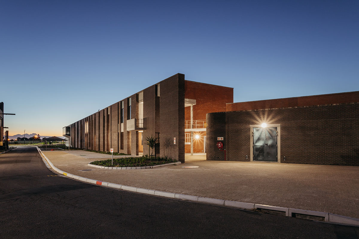
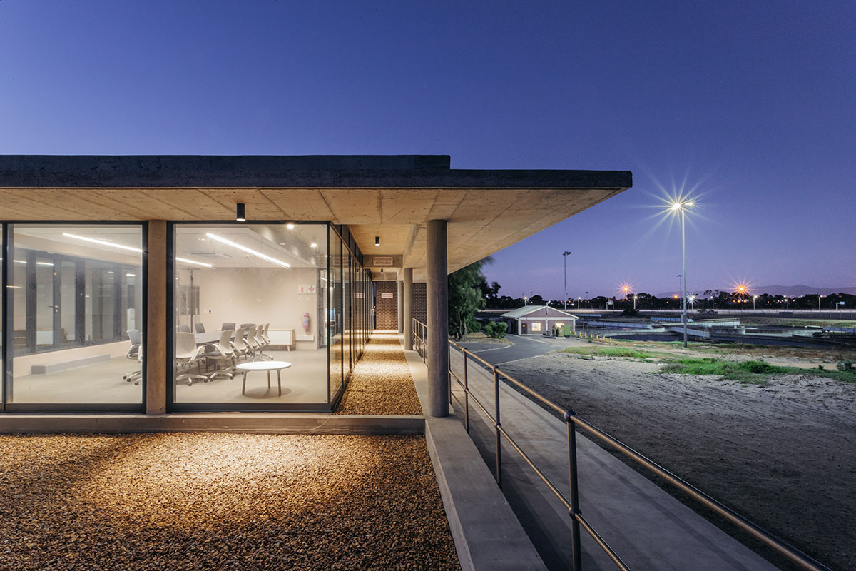
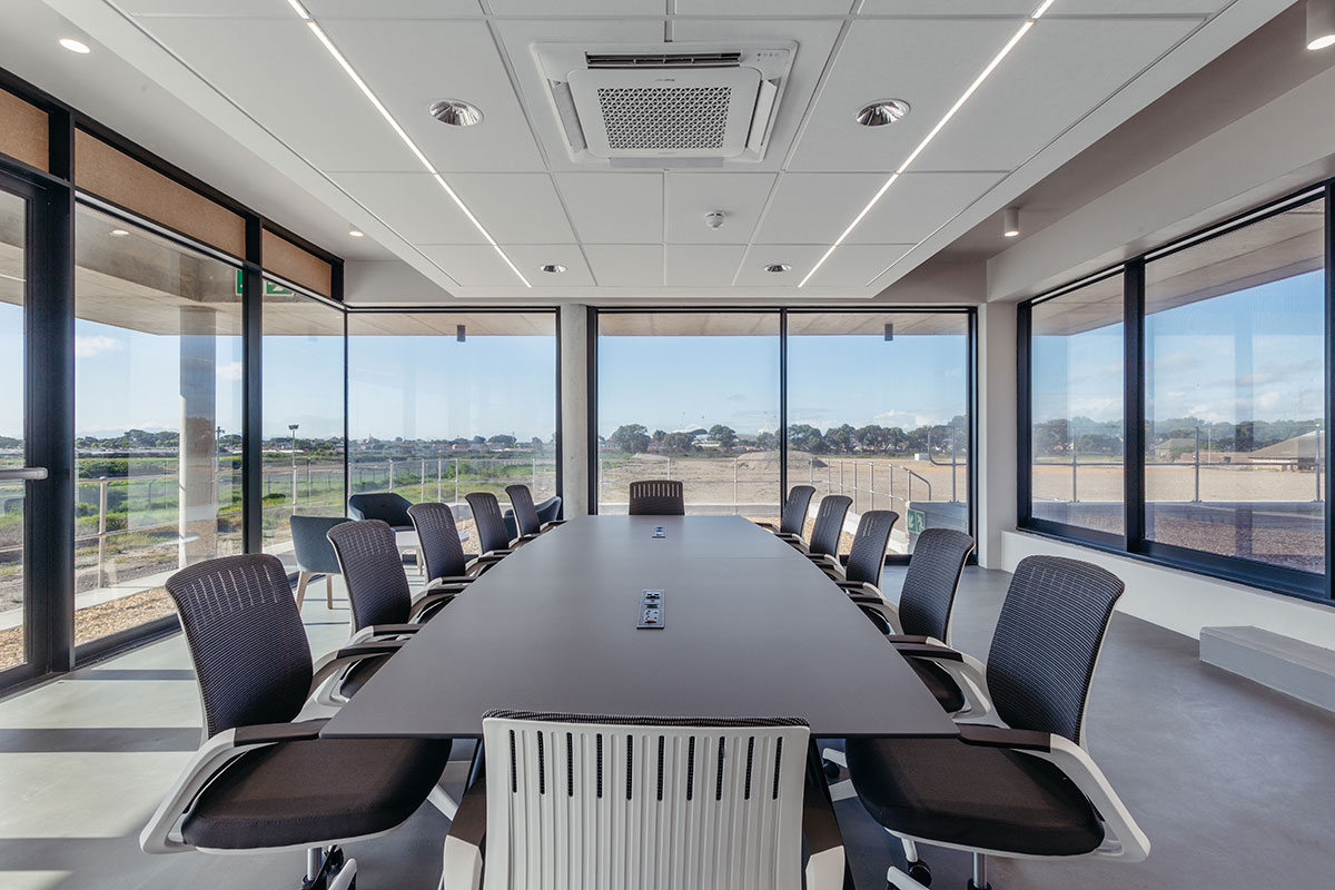
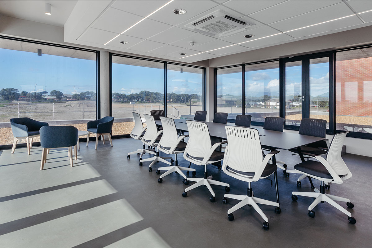
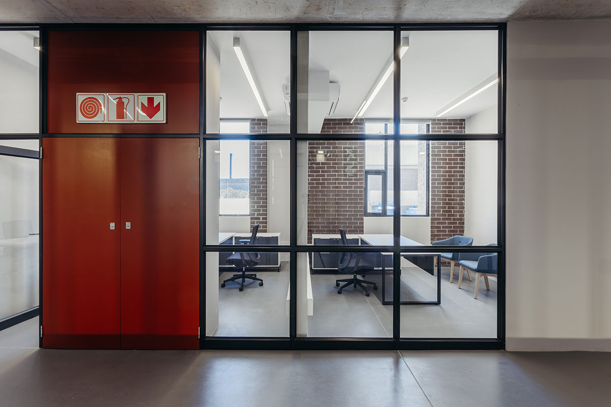
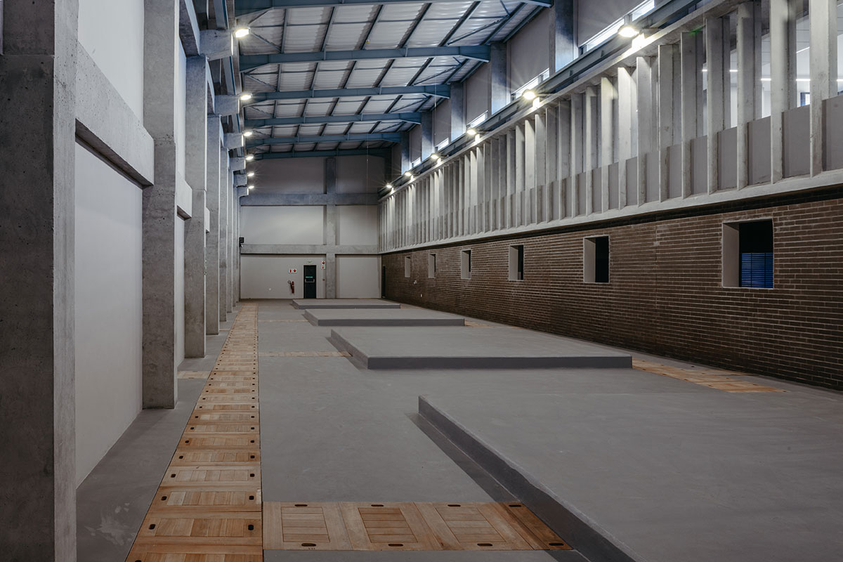
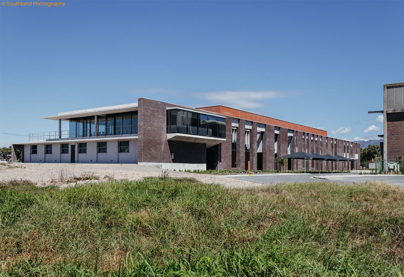
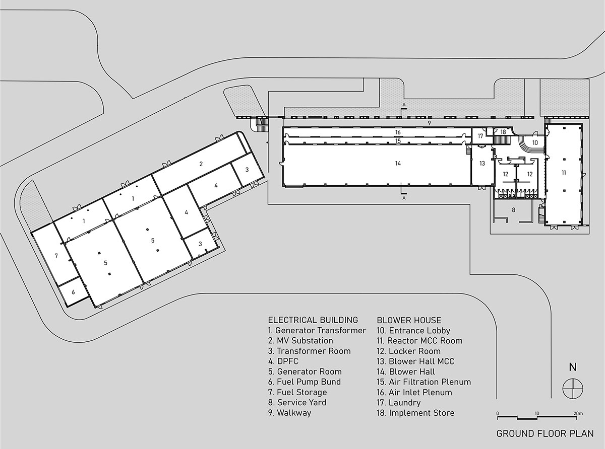
[Text as submitted by architect] The project is a new Blower House Complex on the Athlone Wastewater Treatment Works just outside Cape Town. On the Ground floor, the complex consists of a large blower room with its Motor Control Centre (MCC room) and air plenums, an MCC for the future upgrade’s reactors, locker rooms for the ground staff, a laundry room, and stores. The nature of the first floor is more clerical and includes the control room, SCADA station, offices, boardroom, laboratory, and staff amenities. Connected at an angle to the blower house is the new electrical building which houses four large diesel generators and their associated plant to run the whole plant in case of a power outage.
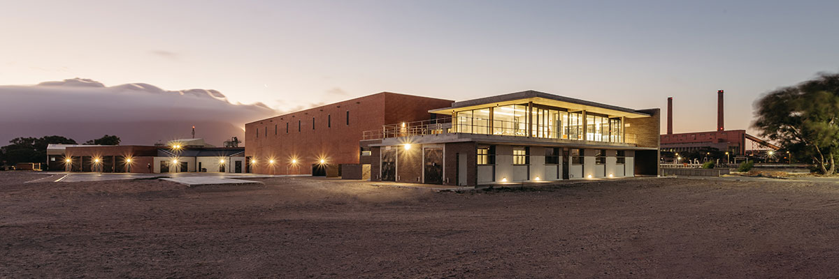
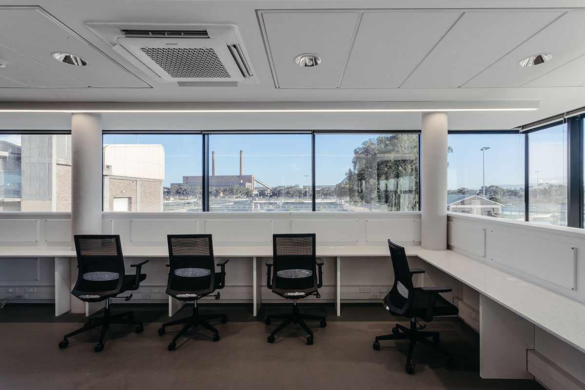
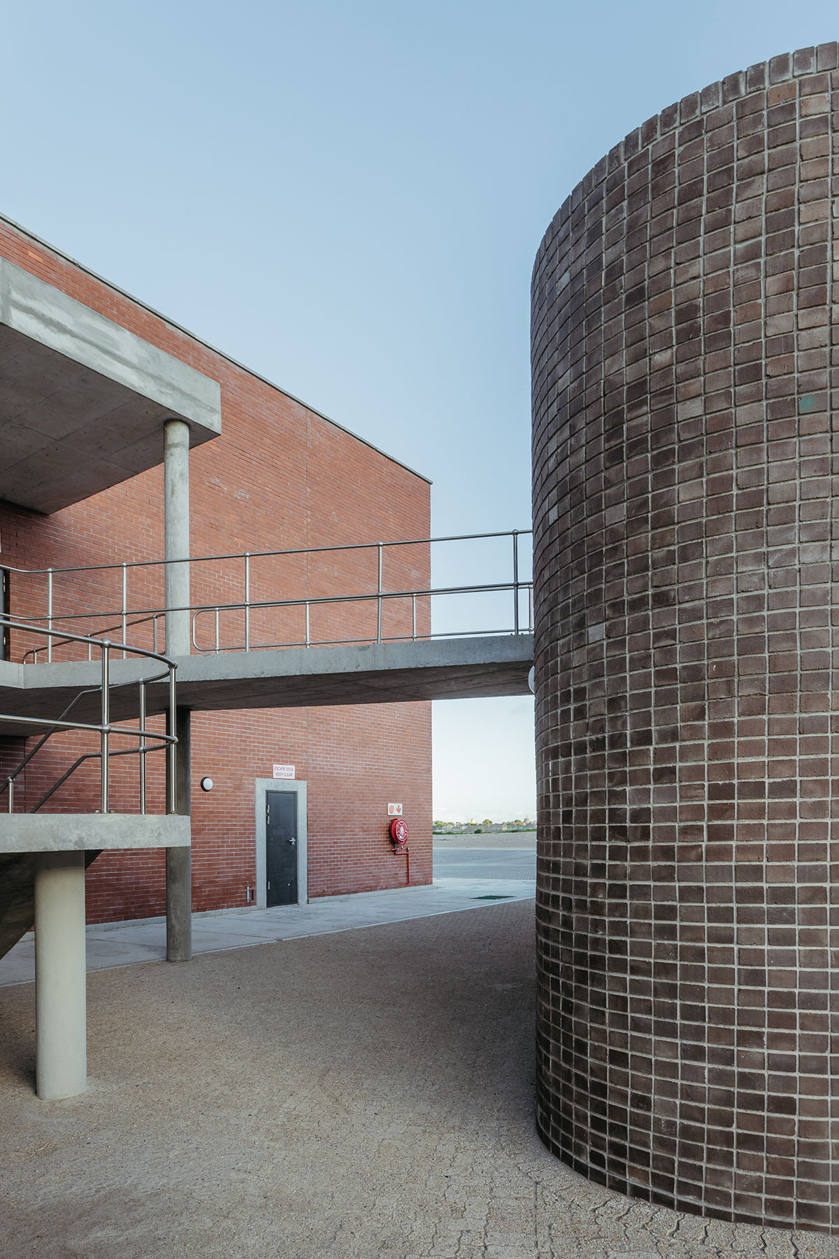
Athlone Wastewater Treatment Works is situated about 10km outside Cape Town’s CBD, next to the N2 highway, one of the main arteries feeding the city. On the other side of the highway are the iconic monolithic red and brown face brick blocks of the remaining old Athlone Power Station, which was decommissioned in 2003. The first wastewater treatment works on the Athlone site were constructed in 1921, extended in 1939, and increased to 36Ml/d in 1952. These old structures are no longer in use but have a presence on site being carefully detailed in rough brown face brick and pre-cast concrete window frames hinting towards the Arts and Crafts movement. The master plan the architects developed for the site proposes to re-purposing these buildings with very exciting new uses in the future.
During the late 70s and early 80s, more stringent legislation led to the modernization of the Works regarding the treatment process, and it was upgraded accordingly to approximately 100Ml/d. The buildings during these upgrades are also in brown face brick but in a modernist way with more exposed concrete structures and bullnose roof sheet details.

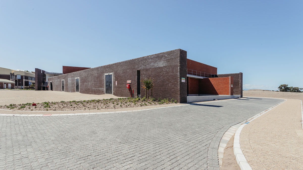
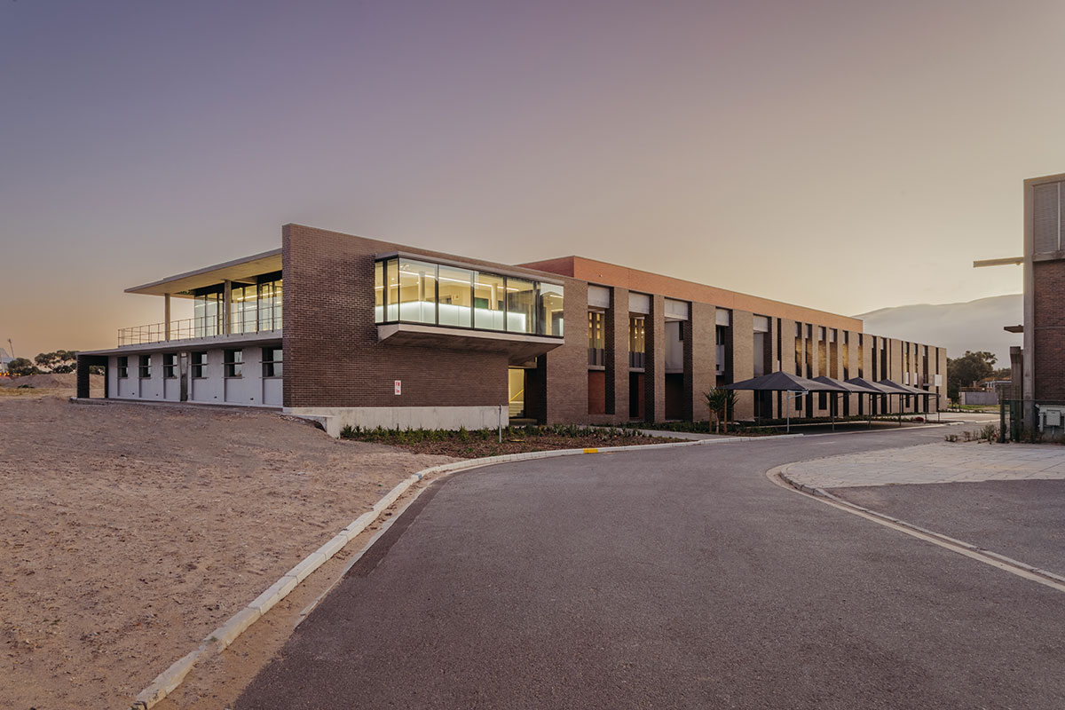
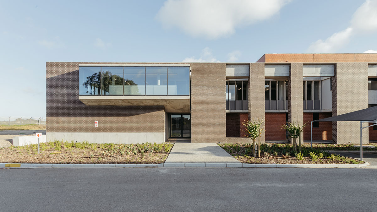
Including accommodating the required functions, the new building was to bear an image of progress for the City, being visible from the highway close to the city centre; be a place that plant staff can take pride in; optimise the flow of staff on the site; and provide observation opportunity over all previous and future plant sections from the control room. Being the first step in the planned 50Ml/d upgrade, the new blower house aims to fit in among the infrastructure relics while establishing a new standard for material use and detailing that exudes the City’s pride in their works without the burden of excessive maintenance.
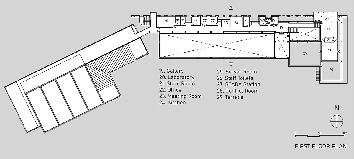
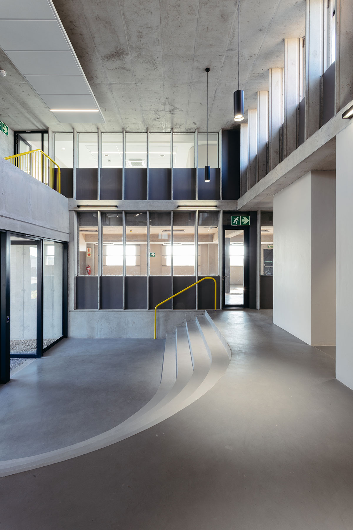
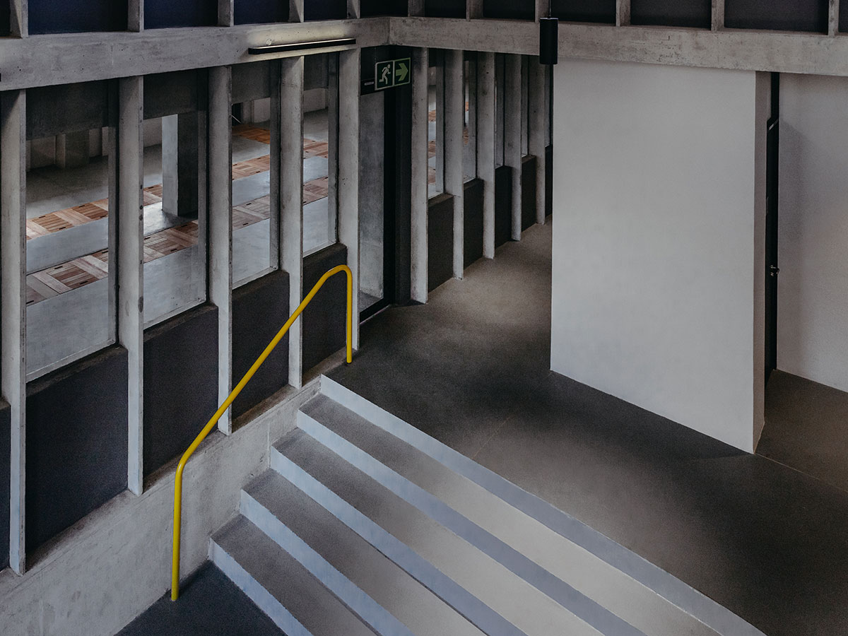
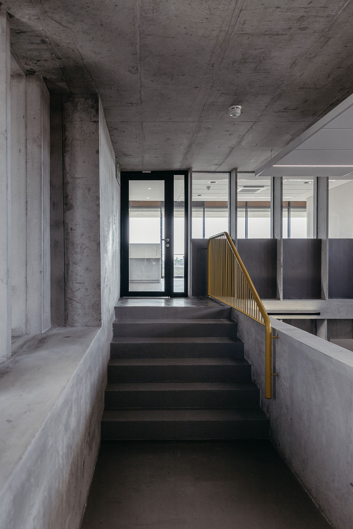
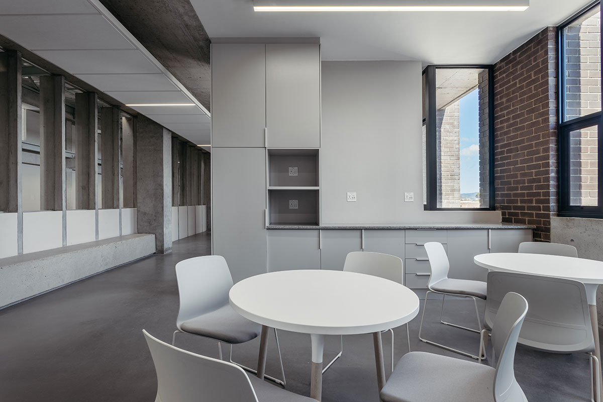
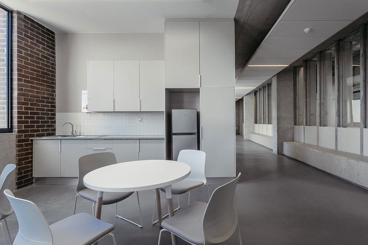
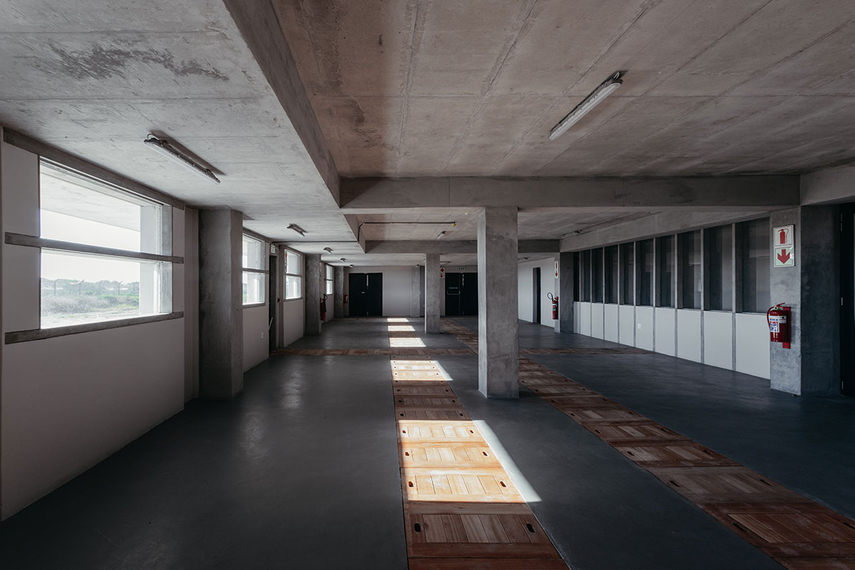
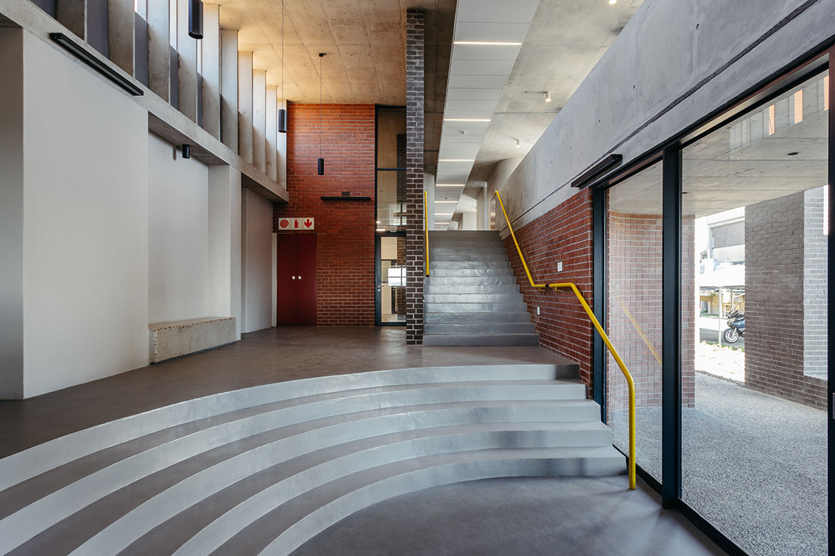
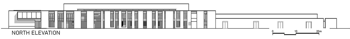
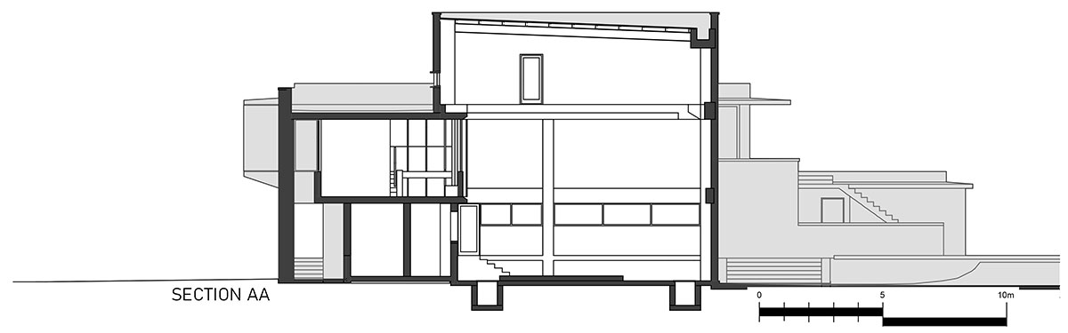
The layout of the planned large civil infrastructure development like the future reactors, settling tanks, roads, and channels, determined the general positioning of the building mass. Fortunately, that caused the long façade to be orientated North. Further to creating optional user space in terms of sunlight and spatial qualities, we wanted to celebrate the primary function of the building which is the plant. A first-floor gallery was created along the north façade, flowing from a generous stair in the entrance lobby. On the one side, the gallery borders the blower hall, and continuous glazing allows views down to the blowers, and on the other side, the staff-related functions are dispersed in a way that is focused on the value of the spaces in between the functions to be useful and pleasant as well as allowing the linear gallery to be a place rather than just a hallway for circulation.
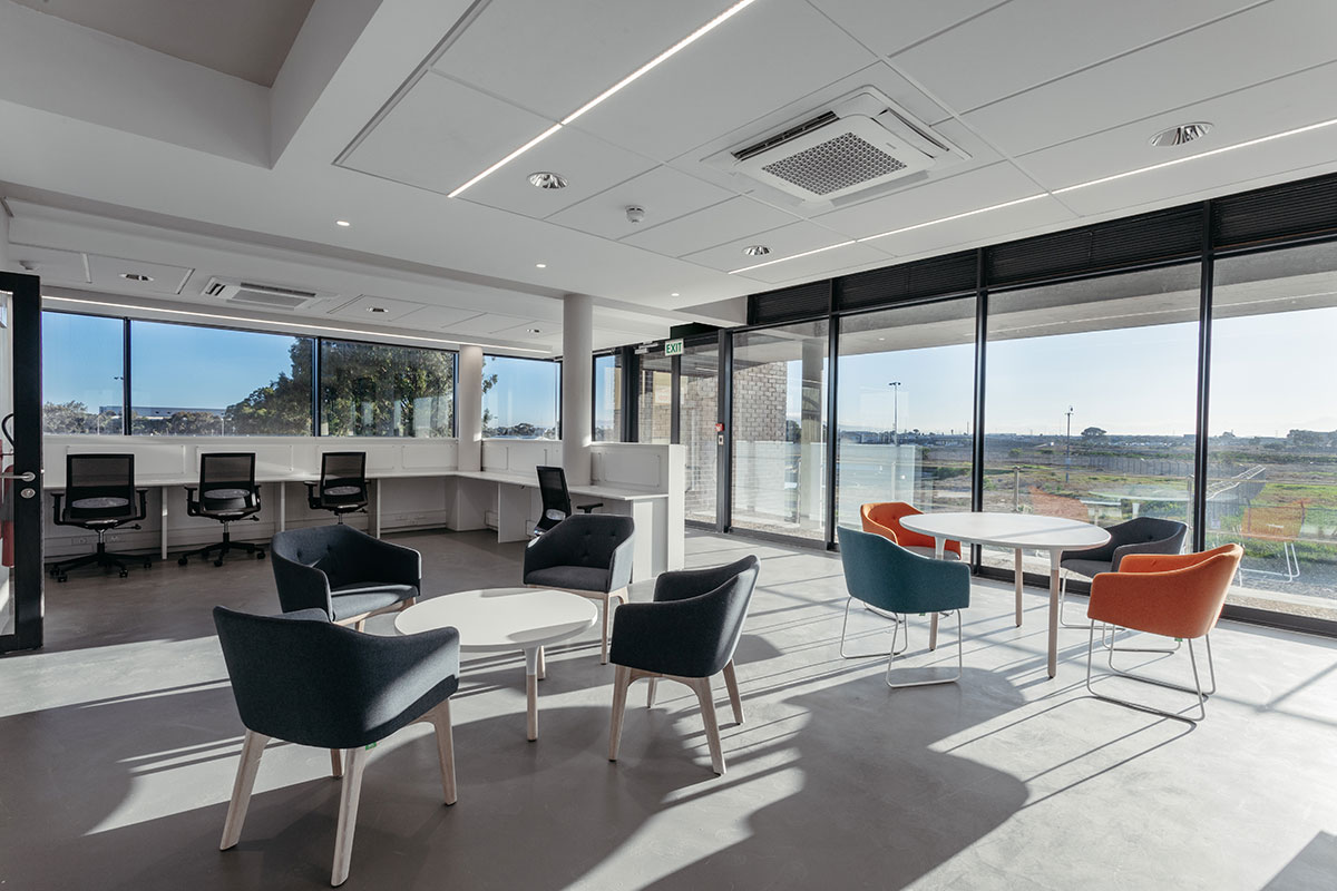
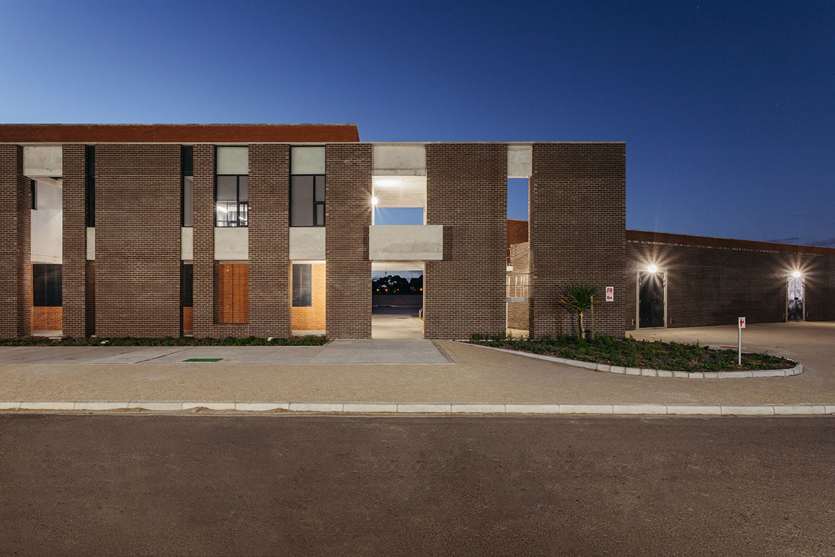
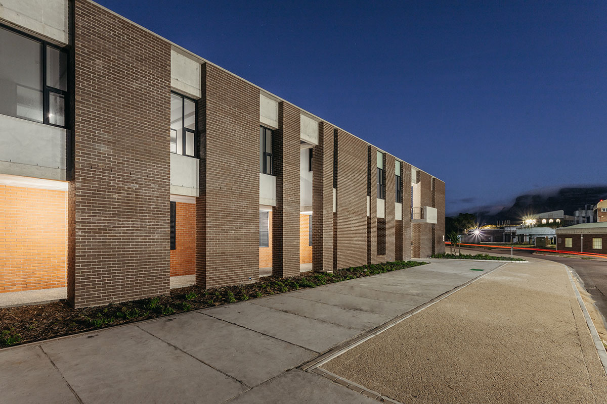
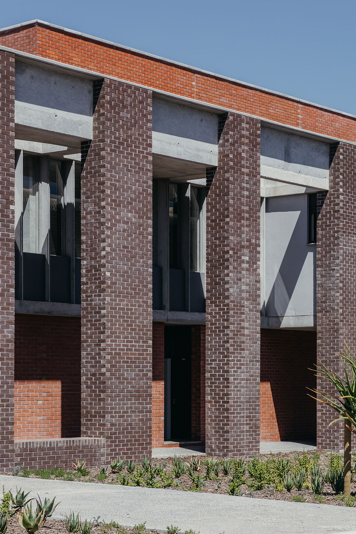
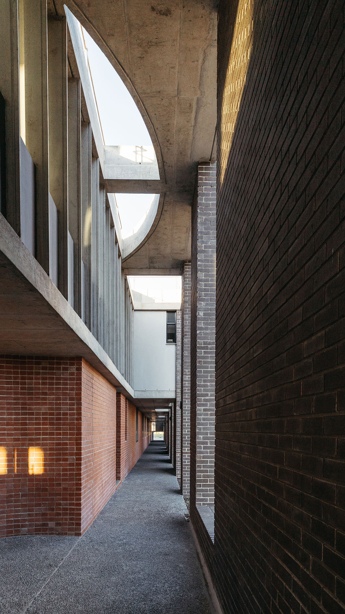
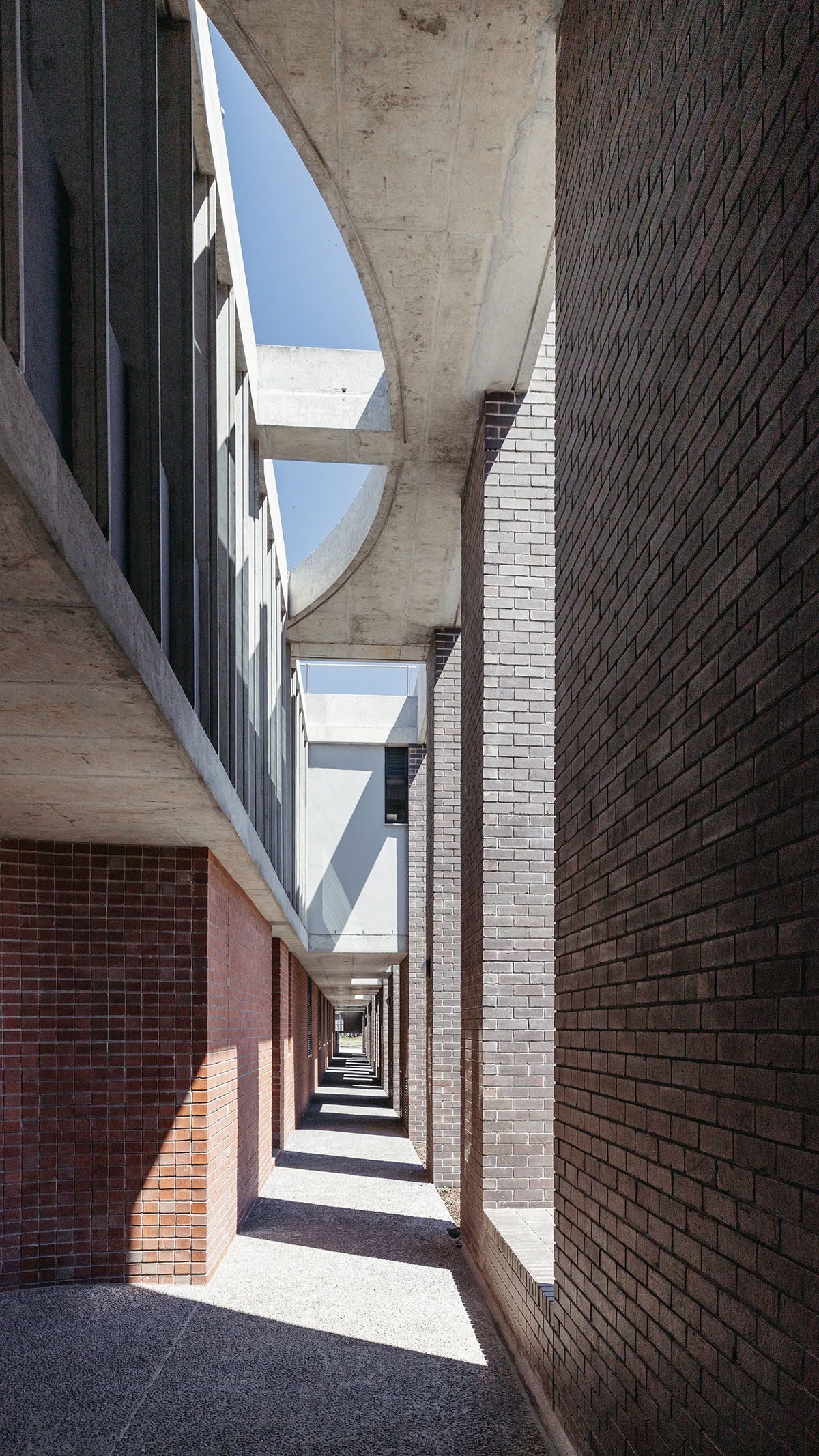
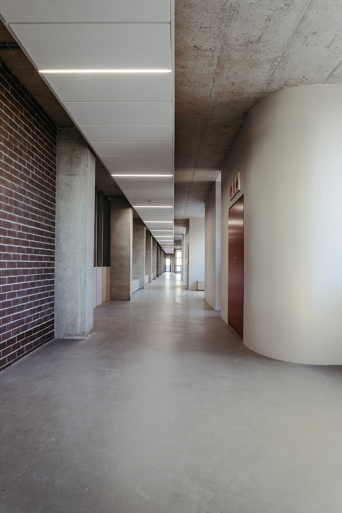
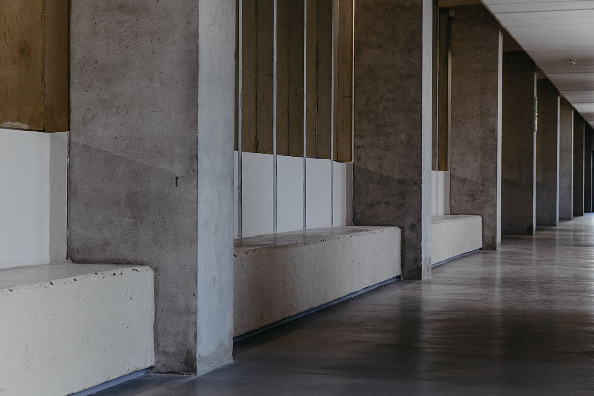
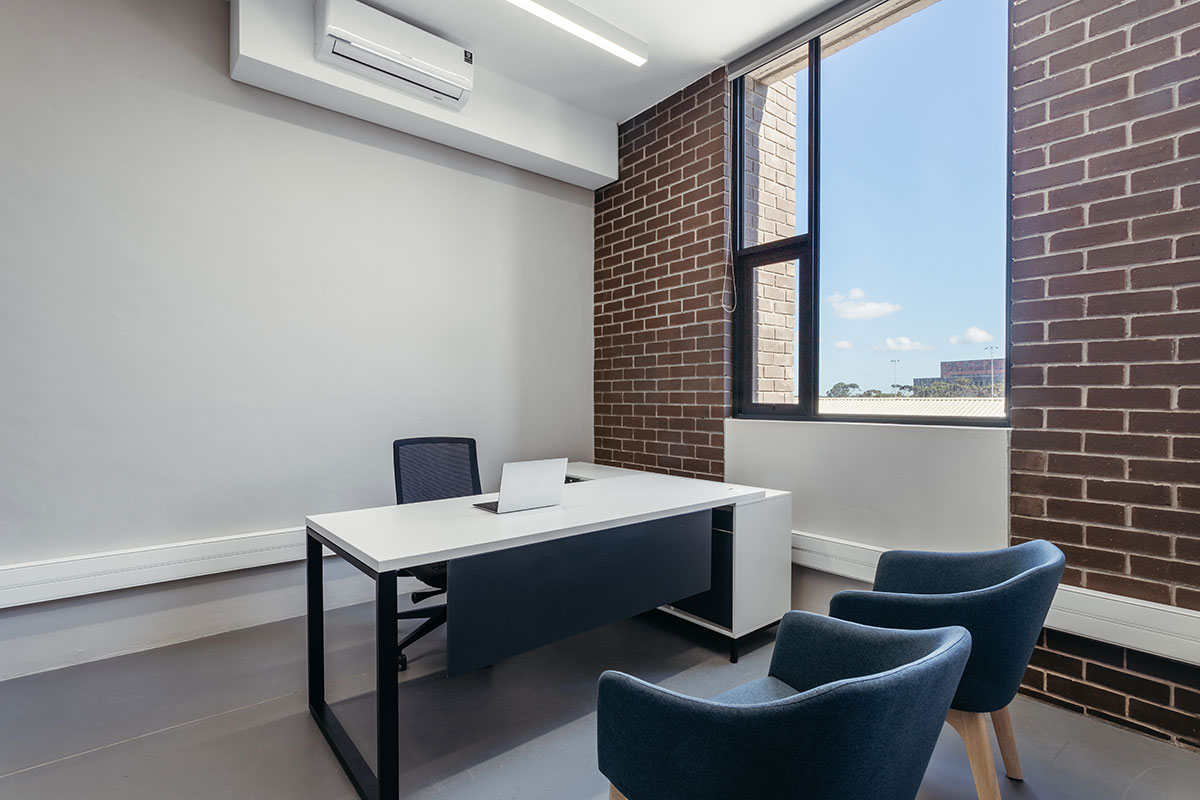
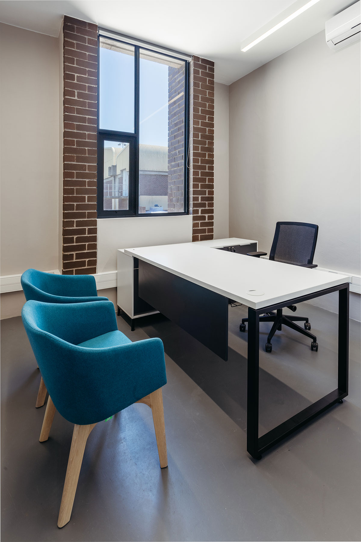
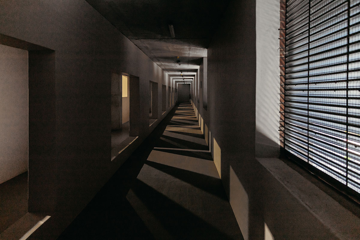
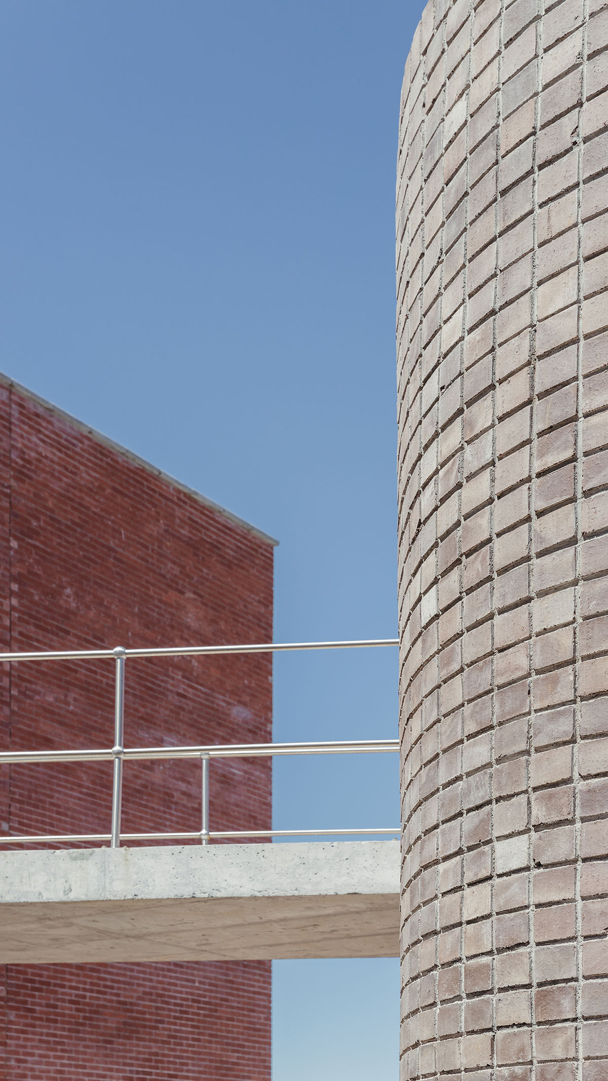
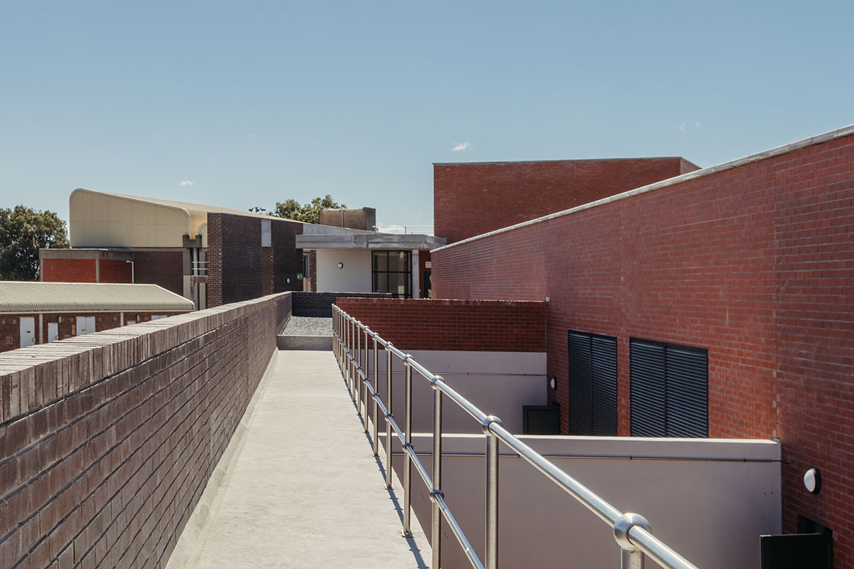
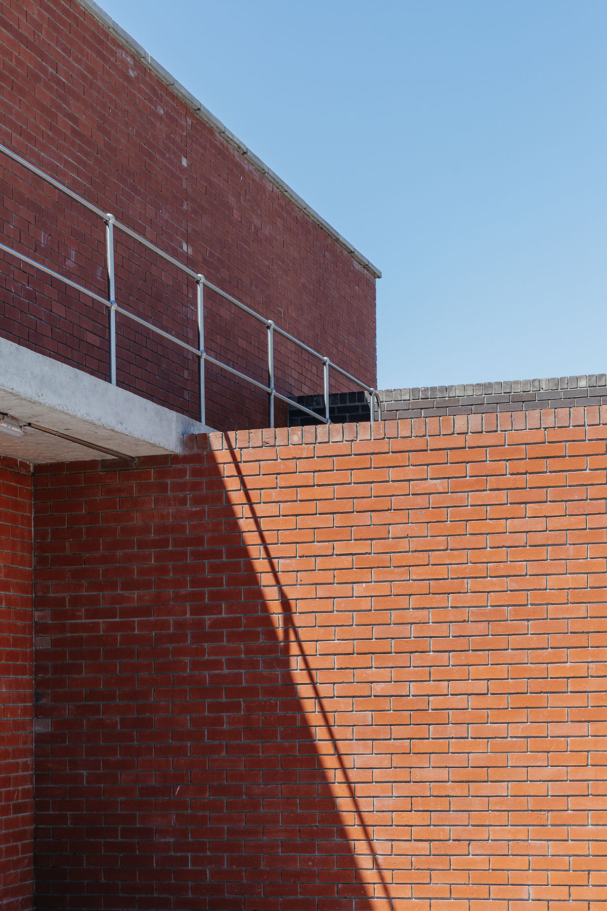
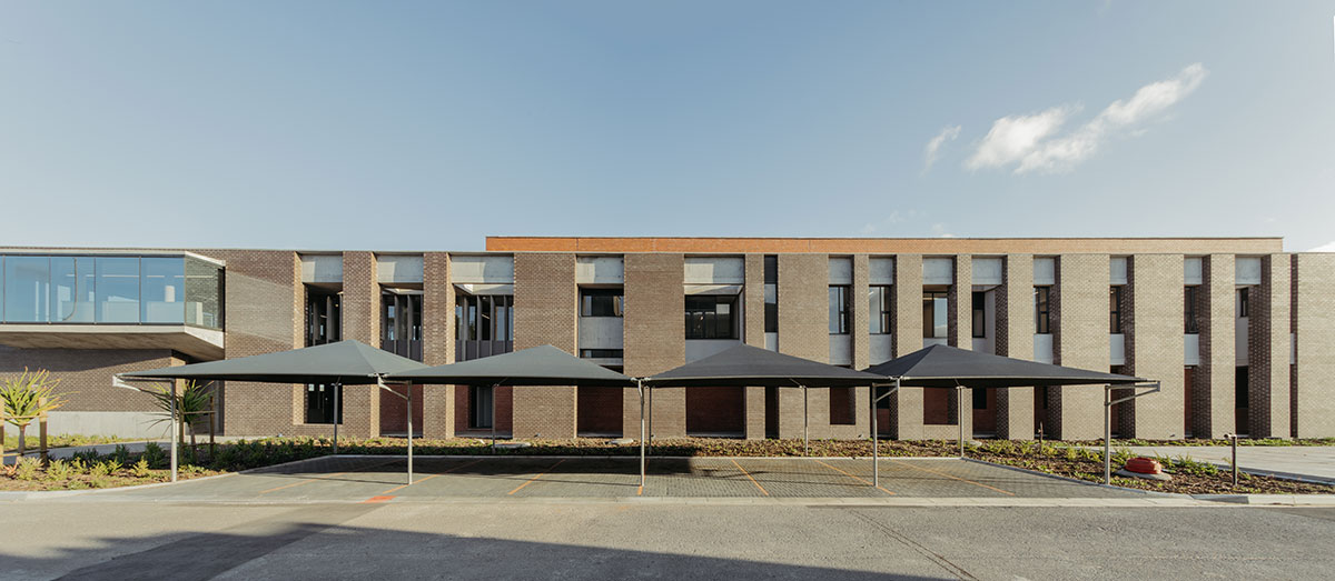
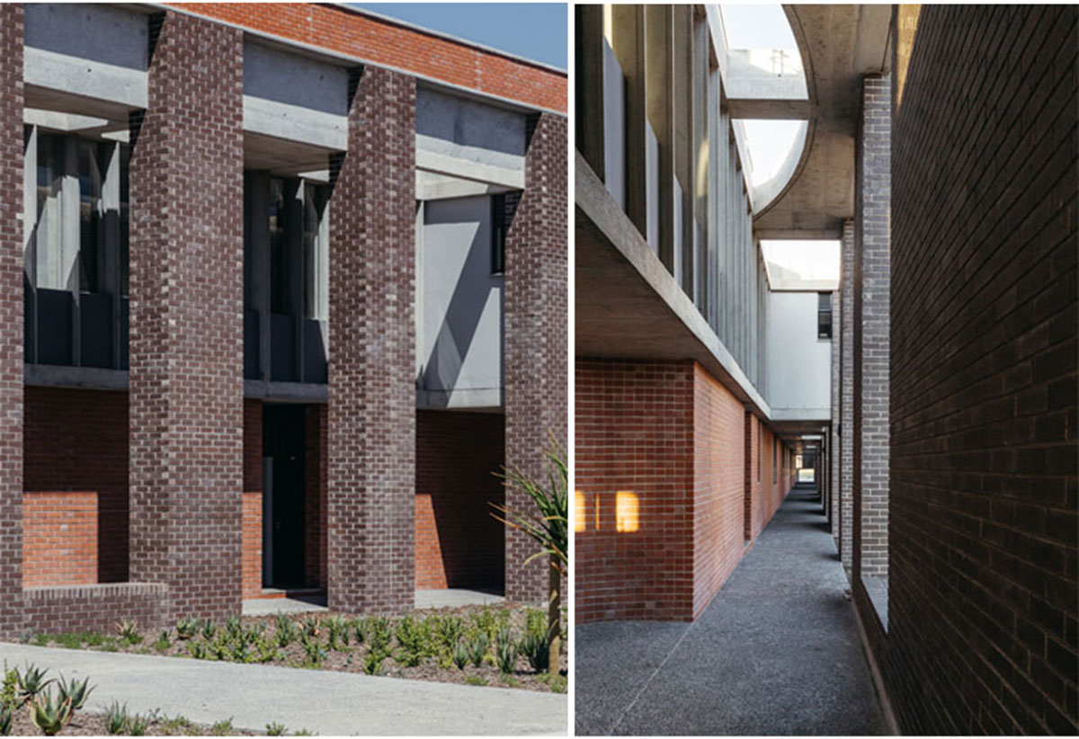
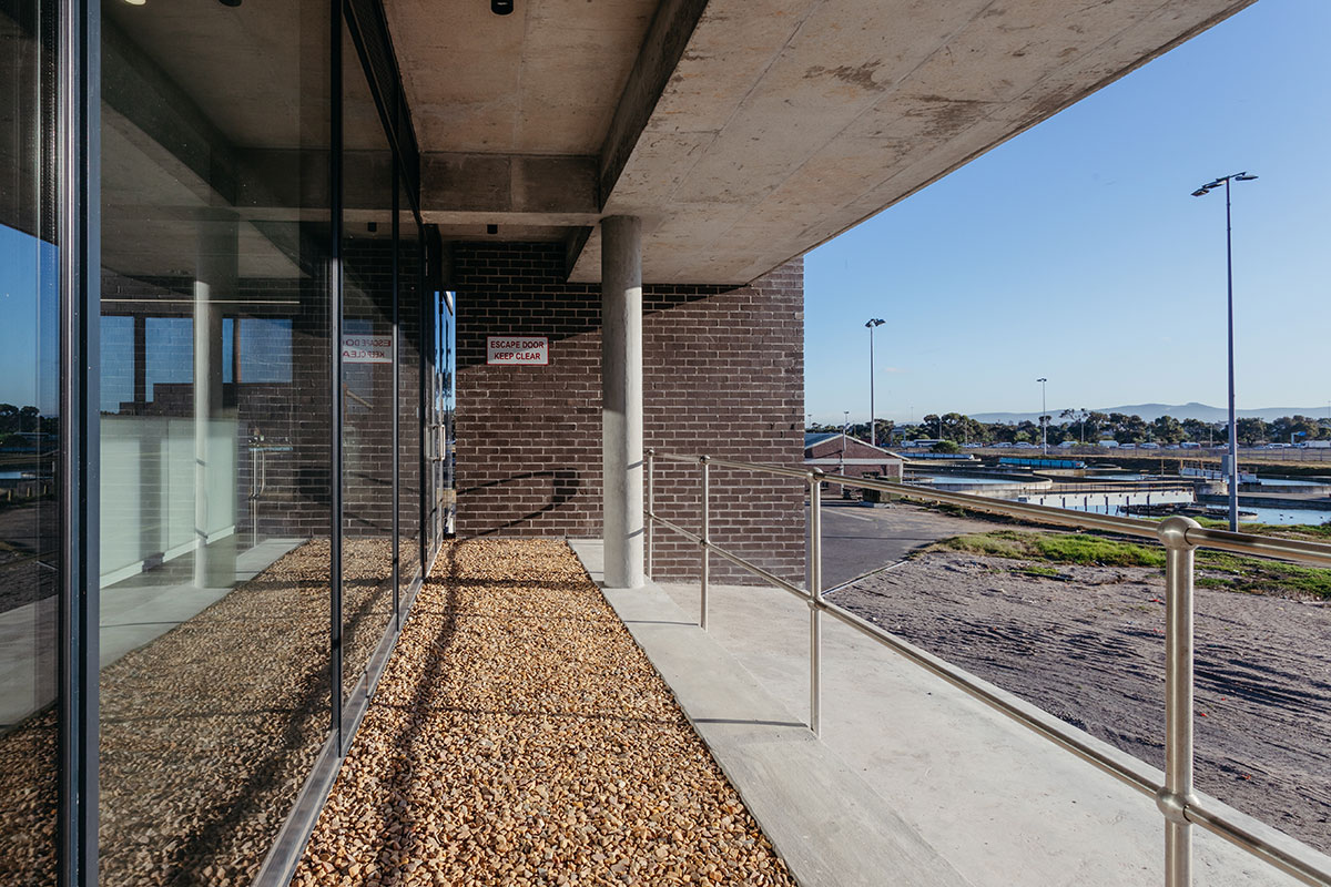
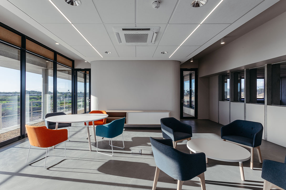
The first floor’s clerical functions and gallery were layered on the northern façade by placing a thick brown eroded face brick wall pane along the northern edge. This element is lower than the blower hall, and carved out around the internal human functions, reinforcing the human scale in a machine-dominated context. On the ground floor, a covered walkway was created on the inside of this element, protecting one from the elements and leading the user to the main entrance through a path of varying character by allowing glimpses of the internal functions, and constantly changing volume and light, as the first floor and roof slab above reacts in various ways to their respective conditions. On the first-floor gallery, the functional elements push to the northern edge in search of optimal sunlight. Some portions of the gallery join this pursuit, creating sitting and meeting areas of varying degrees of intimacy. The functions are as open as possible toward the gallery so that the uses overlap, and the gallery becomes part of the kitchen, laboratory, meeting areas, etc. At the control room on the eastern edge, the SCADA (supervisory control and data acquisition) station pushes its head through the brown face brick skin without touching it on either side. It announces the main entrance underneath it and enables the operators to observe the majority of the plant. Behind the brown face brick façade, the blower hall rises higher in red face brick expressed as a masonry box.
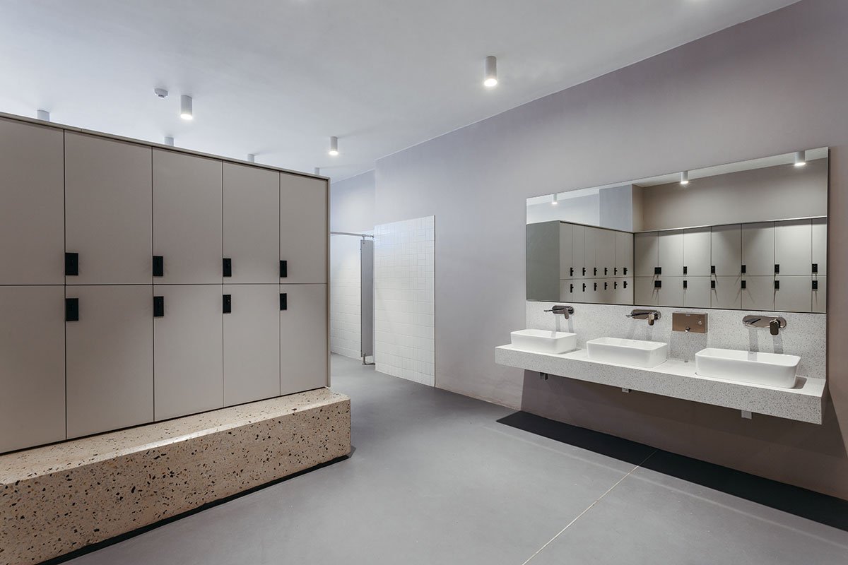
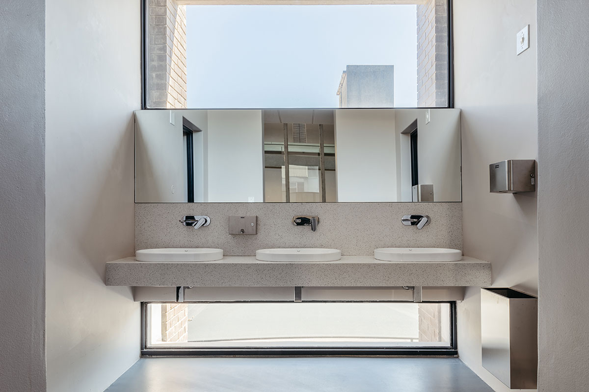
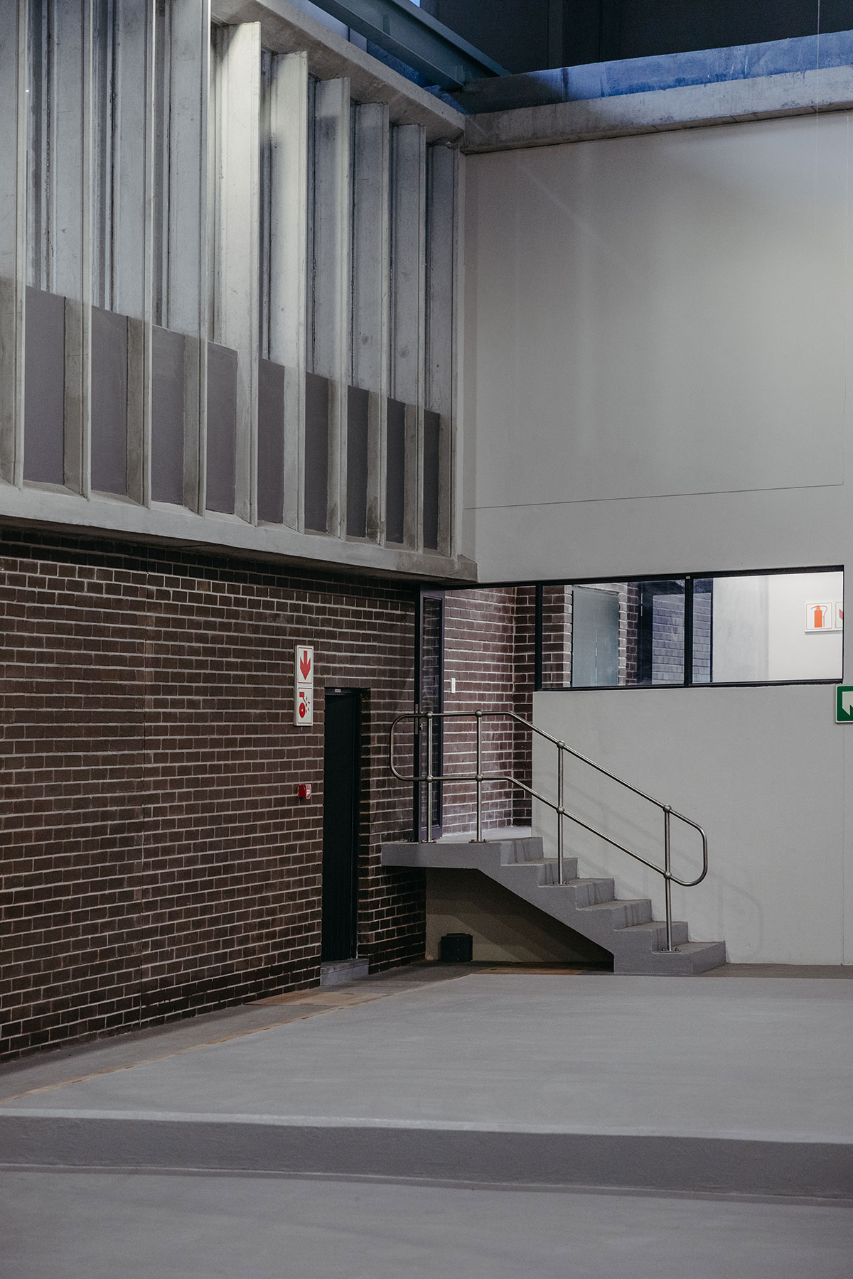
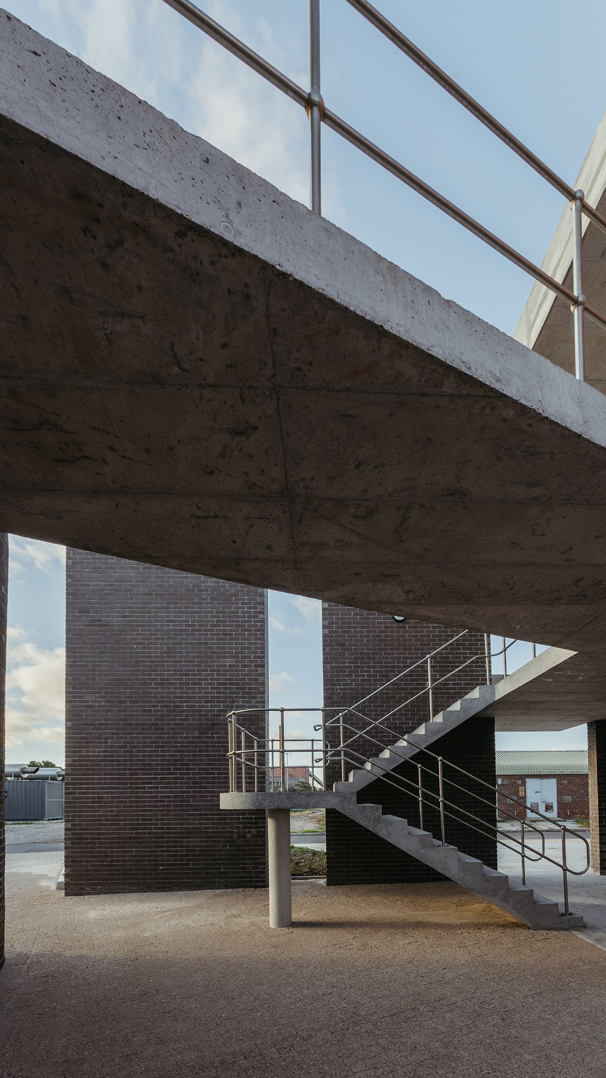
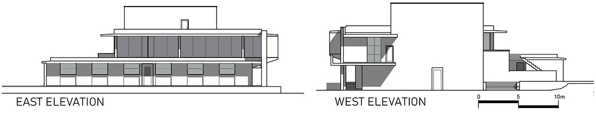
The circulation of staff on the plant was carefully considered with the layout. The ground staff is physically working around all areas of the plant in 8h shifts around the clock. The locker rooms, laundry, and MCC rooms were placed on the ground floor to limit treading dirt from the grounds into the building. The cleaner clerical functions are separated from the grounds on the first floor and can be accessed after donning clean outfits at the ground floor locker rooms. The laboratory is used by both office and ground staff, testing samples collected all over the plant. It was placed on the furthest end of the first-floor gallery and a spacious secondary access point was introduced at the end of the gallery with a wide concrete stair and external balcony peeking through the brown face brick skin. It doubles as the escape door at the western end of the building.
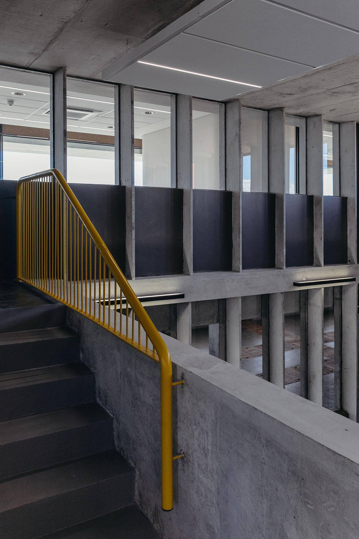
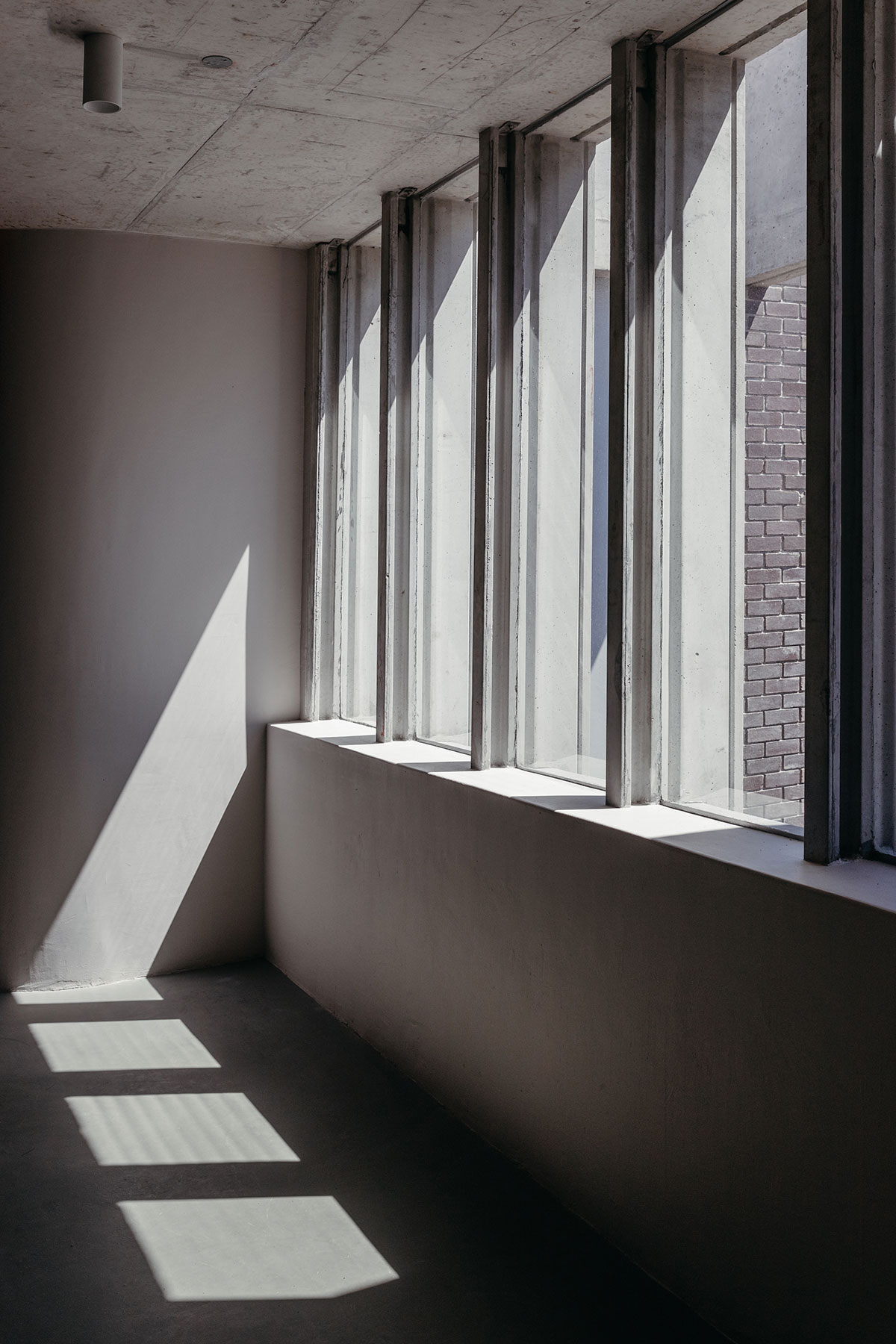
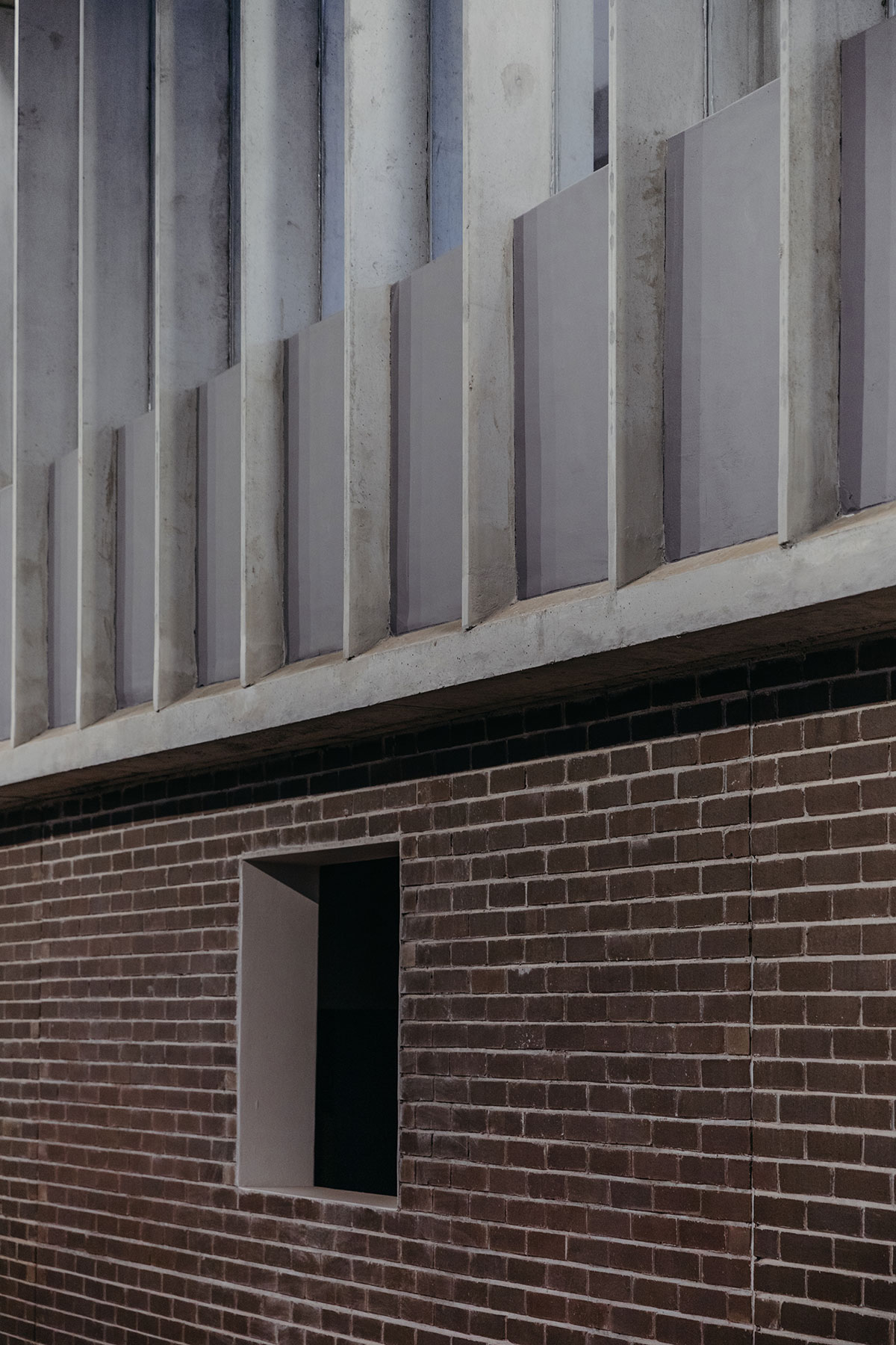
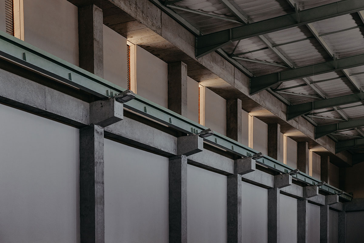
Another key challenge of the site is the extremely corrosive nature of a wastewater environment. Inspired by the old plant buildings’ pre-cast concrete windows, a pre-cast concrete window fin profile was implemented. This proprietary Wintec Innovation product was originally designed to function as a lintel over openings in masonry walls. Cast-in rebates provide a surface onto which the glazing can be directly fixed with polyurethane, obviating the need for frames in any other material that can corrode or wear out. The fins were turned vertically, and fixing details developed, stiffening it with infill brick spandrel panels at the bottom sections and fixed glazing panels glued into the top section, resulting in a very satisfying internal vertical material expression and identity of the internal architecture.
Drawings
Images